individual assignment for this week:
Add an output device to a microcontroller board you've designed, and program it to do somethinggroup assignment:you can chak here
measure the power consumption of an output deviceWhat Is an Output Device?
An output device is a piece of computer hardware that receives data from a computer and then translates that data into another form. That form may be audio, visual, textual, or hard copy such as a printed document.
In output weekI designed a special board for this week, which corresponds to the two experiments carried outI use servo motor with Potentiometer, And in the second experiment, we used LED strip and light control.
I started designing a special board for this week
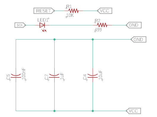
After adding atmega328p I made the appropriate connections and added a crystal 16MHz because crystal devices such as quartz crystal units and quartz crystal oscillators have high stability against an environment change such as temperature, they are used as frequency control devices in electronic circuits.

Here I added the pins for the components I used as shown below, in addition to the ISP for programming the board.
I added an LED, it lights up when programming the board, and I added three capacitors in parallel to keep the circuit stable.
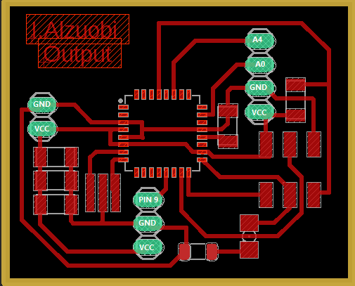
After I finished adding all the circuit components I moved on to the panel design stage, the result is as shown below
After completing the board design, I imported the design images to Adjust settings on Fab Modules

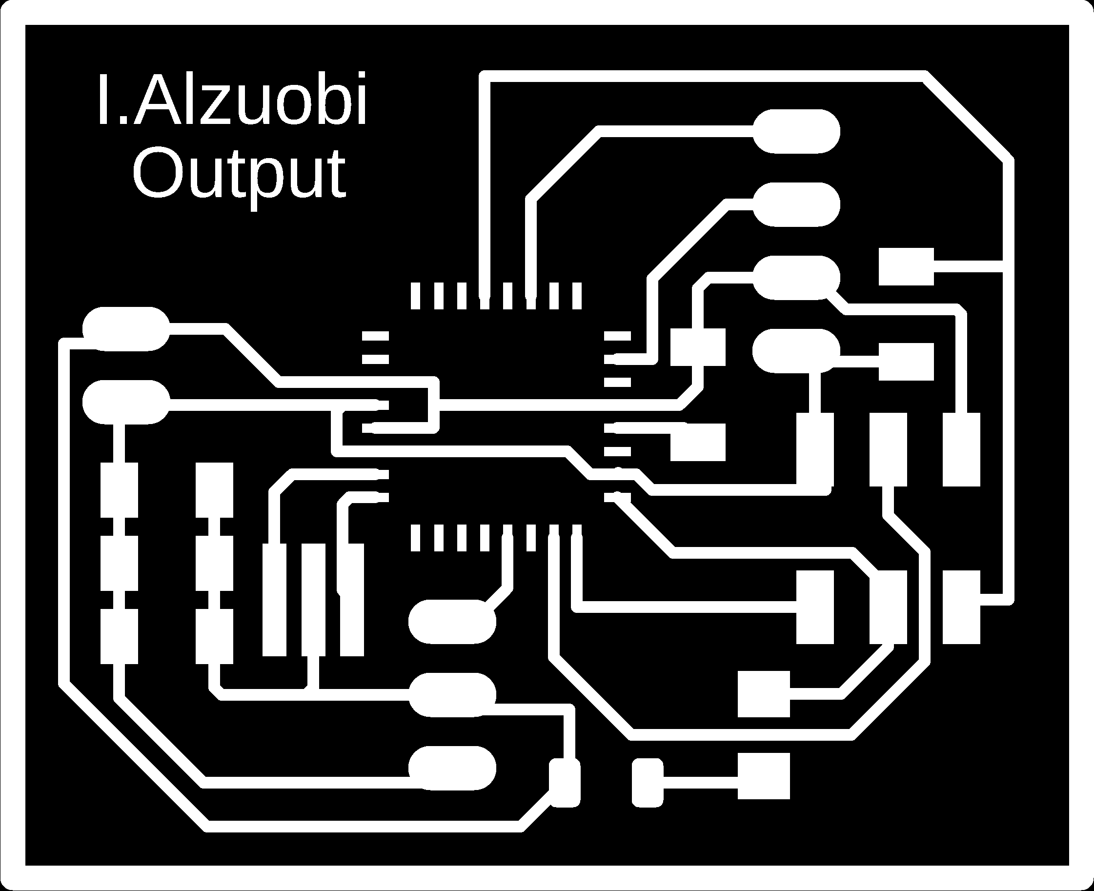
Settings Fab modules
OutLine Settings


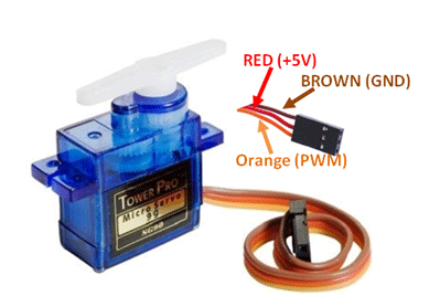
I controlled the servo motor with variable resistance, And the connections were as follows
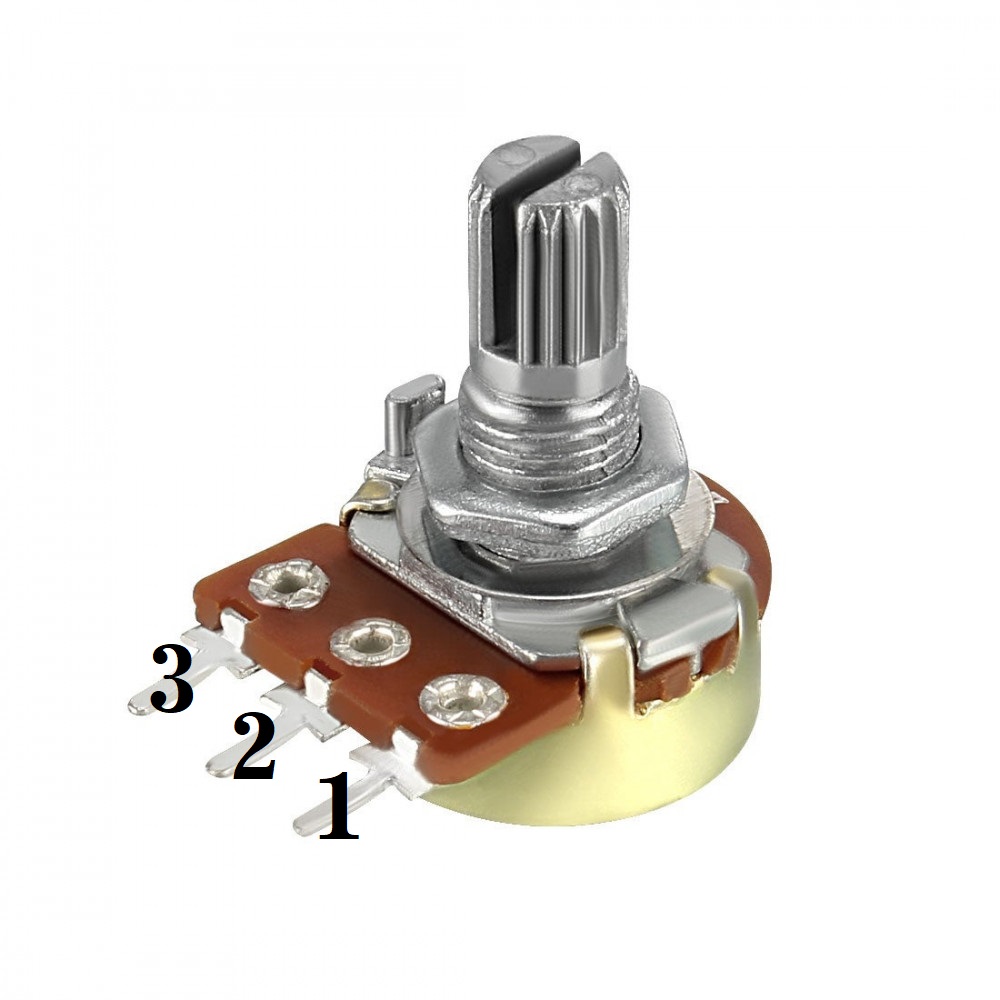
- Potentiometer
- pin1 with GND
- pin2 with A4
- pin3 with +5V
- servo motor
- Brown with GND
- Red with VCC
- Orange with pin 9
This is the Arduino code
#include

Servo myservo;  // create servo object to control a servo

int potpin = A4;  // analog pin used to connect the potentiometer
int val;    // variable to read the value from the analog pin

void setup() {
  myservo.attach(9);  // attaches the servo on pin 9 to the servo object
}

void loop() {
  val = analogRead(potpin);            // reads the value of the potentiometer (value between 0 and 1023)
  val = map(val, 0, 1023, 0, 180);     // scale it to use it with the servo (value between 0 and 180)
  myservo.write(val);                  // sets the servo position according to the scaled value
  delay(15);                           // waits for the servo to get there
}
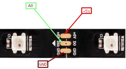
I used this week's task to LED a tape and program it to make a specific light using the final project board Thus the circuit is connected
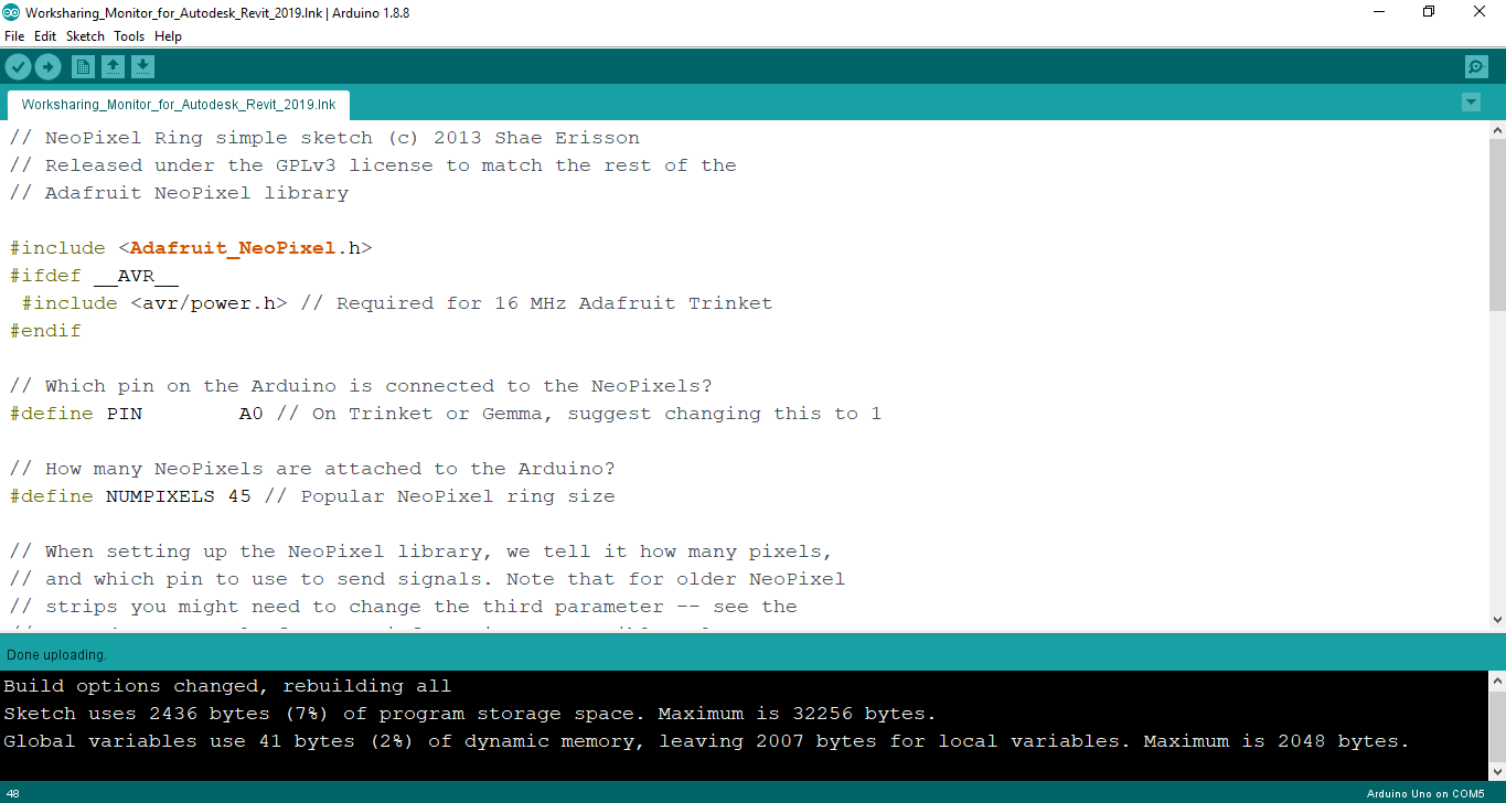
This is my code
#include
#ifdef __AVR__
 #include  // Required for 16 MHz Adafruit Trinket
#endif

// Which pin on the Arduino is connected to the NeoPixels?
#define PIN        A0 // On Trinket or Gemma, suggest changing this to 1

// How many NeoPixels are attached to the Arduino?
#define NUMPIXELS 45 // Popular NeoPixel ring size

// When setting up the NeoPixel library, we tell it how many pixels,
// and which pin to use to send signals. Note that for older NeoPixel
// strips you might need to change the third parameter -- see the
// strandtest example for more information on possible values.
Adafruit_NeoPixel pixels(NUMPIXELS, PIN, NEO_GRB + NEO_KHZ800);

#define DELAYVAL 500 // Time (in milliseconds) to pause between pixels

void setup() {
  // These lines are specifically to support the Adafruit Trinket 5V 16 MHz.
  // Any other board, you can remove this part (but no harm leaving it):
#if defined(__AVR_ATtiny85__) && (F_CPU == 16000000)
  clock_prescale_set(clock_div_1);
#endif
  // END of Trinket-specific code.

  pixels.begin(); // INITIALIZE NeoPixel strip object (REQUIRED)
}

void loop() {
  pixels.clear(); // Set all pixel colors to 'off'

  // The first NeoPixel in a strand is #0, second is 1, all the way up
  // to the count of pixels minus one.
  for(int i=0; i
    // pixels.Color() takes RGB values, from 0,0,0 up to 255,255,255
    // Here we're using a moderately bright green color:
    pixels.setPixelColor(i, pixels.Color(0, 150, 0));

    pixels.show();   // Send the updated pixel colors to the hardware.

    delay(100); // Pause before next pass through loop
  }
}
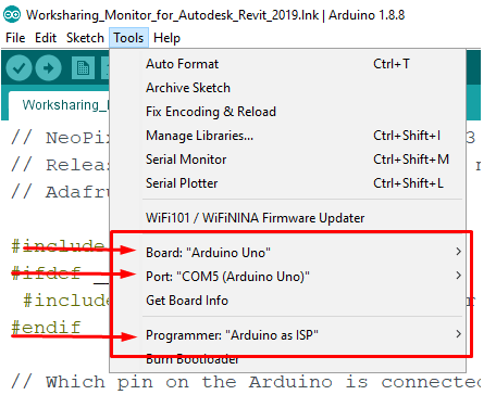
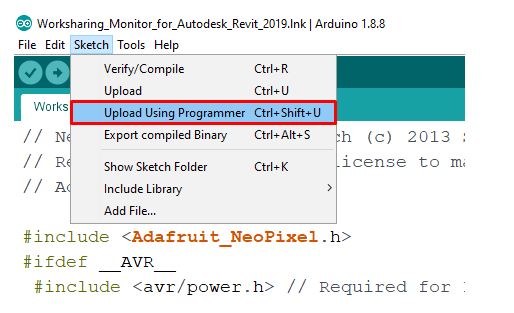
After writing the programming code, upload it to the board through the settings as it appears in the image
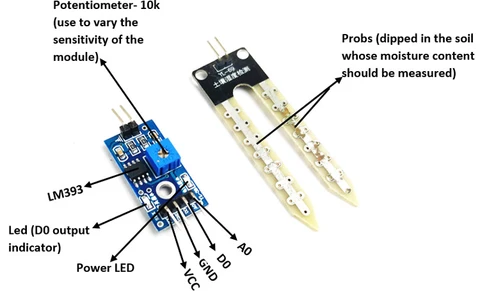
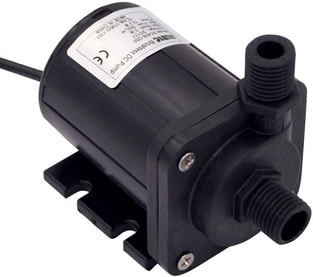
In addition to the final project, I did an experiment with a humidity sensor and a pump
int motor =6;
int sensor_pin =13;


void setup() {
  pinMode(motor, OUTPUT);
  pinMode(sensor_pin, INPUT);
}


void loop() {

  if(digitalRead(13) == HIGH)
  {
    digitalWrite(6, HIGH);
  }


  else
  {
    digitalWrite(motor, LOW);
  }


}
This video shows how the pump stops working when it reads the required humidity level and the water cup in the video is for testing only
You can download all codes click here
For download schematicsfor my board check here
int motor =6;
int sensor_pin =13;
void setup() {
pinMode(motor, OUTPUT);
pinMode(sensor_pin, INPUT);
}
void loop() {
if(digitalRead(13) == HIGH)
{
digitalWrite(6, HIGH);
}
else
{
digitalWrite(motor, LOW);
}
}